Week 7
Now that I have pretty much decided on creating an alarm clock-esque device for my final project, I wanted to start incorporating components of my final project into my weekly assignments. With this week having an open-ended assignment where we explore various output devices, it seemed like the perfect assignment to start with.
In particular, I decided to use an LCD Display and Piezo Buzzer as my output devices and a button and ESP32 as the devices providing input. Ultimately, I was able to use these devices to create a simple 30 second timer that can be reset using a button.

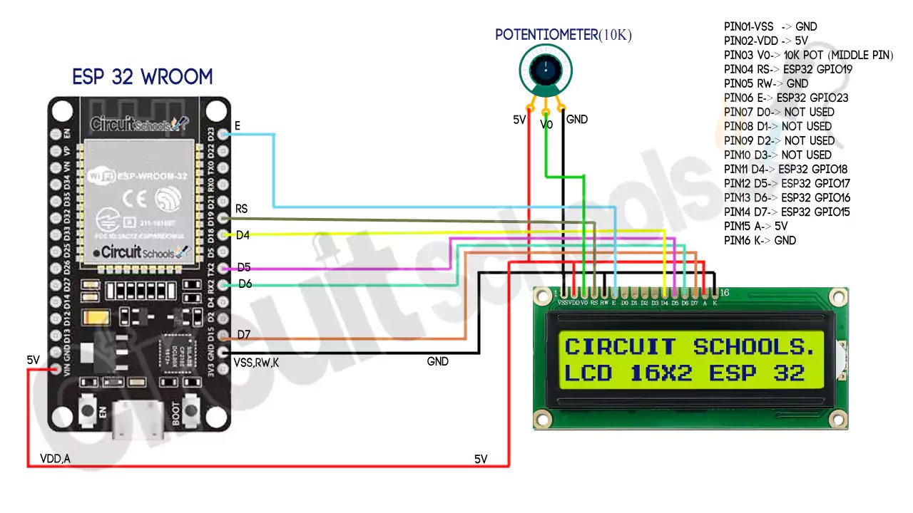
Image Credit: Circuit Schools
However, as the circuit above demonstrates, wiring the LCD component in particular proved to be unexpectedly challenging. To save time and to allow me to correct if I made any mistakes, I decided to use clips as opposed to soldering the wires. However, this made the circuit quite unstable, and I will certainly be soldering the wires for my final project.
Luckily, once the LCD was wired, integrating the button and Piezo buzzer proved to be relatively straightforward. While I did have some slight difficulties integrating the ESP32 into my project for the first time, I think that having such a capable and small microprocessor will ultimately be quite beneficial!
Programming
Seeing as this project had various different components, I decided to encapsulate the code for the LCD, buzzer, and button into respective classes. This allowed me to abstract away any unnecessary details about the devices themselves and to allow for simultaneous input/output.
Given the complexity of the components I was using, I also chose to make use of pre-built functions and libraries. In particular, for the LCD, I used the LiquidCrystal library which allowed me to easily print text to the screen. For the buzzer, I used the tone() and noTone() functions, which allowed me to play a simple tune when the timer was done. Finally, for the button, I used the digitalRead() function, which allowed me to read the state of the button in the pullup resistor circuit.
Lastly, I imported standard notes from a "pitches.h" file and started a timer using the millis() function. With some more troubleshooting, the project was soon ready to go! For reference, the full code for this timer is provided below:
    #include "pitches.h"
    #include <LiquidCrystal.h>

    const int melody[] = { NOTE_C4, NOTE_G3, NOTE_G3, NOTE_A3, NOTE_G3, 0, NOTE_B3, NOTE_C4 };
    const int times[] = { 4, 8, 8, 4, 4, 4, 4, 4 };
    const int alarmTime = 30000;
    int previousMillis = 0;

    class Button {
      int pin;
      int buttonState;

    public:
      Button(int inputPin) {
        pin = inputPin;
        buttonState = 0;
      }

      int getReading() {
        buttonState = digitalRead(pin);
        return buttonState;
      }
    };

    class Buzzer {
      int pin;

    public:
      Buzzer(int inputPin) {
        pin = inputPin;
        pinMode(pin, INPUT);
      }

      void playTune() {
        for (int thisNote = 0; thisNote < 8; thisNote++) {
          int noteDuration = 1000 / times[thisNote];
          tone(pin, melody[thisNote], noteDuration);

          int pauseBetweenNotes = noteDuration * 1.30;
          delay(pauseBetweenNotes);
          noTone(pin);
        }
      }
    };

    Button button(41);
    Buzzer buzzer(40);
    LiquidCrystal lcd(14, 13, 12, 20, 19, 21);

    void setup() {
      lcd.begin(16, 2);
      lcd.print("Time Remaining:");
    }

    void loop() {
      int status = button.getReading();
      if (status == 1) {
        previousMillis = millis();
        lcd.clear();
        lcd.setCursor(1, 0);
        lcd.print("Time Remaining:");
      }
      if (millis() - previousMillis >= alarmTime) {
        lcd.setCursor(0, 0);
        lcd.clear();
        lcd.print("Time's Up!");
        buzzer.playTune();
        delay(1000);
      } else {
        lcd.setCursor(0, 1);
        int time = (alarmTime - (millis() - previousMillis)) / 1000;
        lcd.print(String(time) + " seconds ");
      }
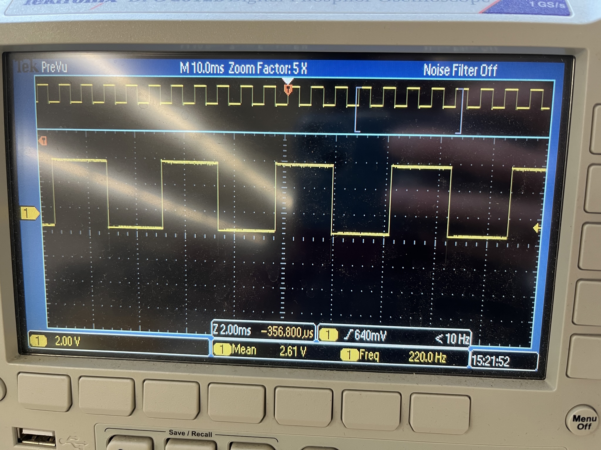
}To gain further insight into the way in which the Piezo Buzzer component of my circuit was operating, I decided to use the oscilloscope. The results of hooking the oscilloscope up to my buzzer while the melody from the code above played is shown below:

As the image above demonstrates, the Arduino is sending square wave signals according to a fixed clock. That is, as a tone is playing, square waves appear. The period of these waves is approximately 23ms, and they appear at regular intervals as a tone is playing. However, when the tone stops, so do the waves. Indeed, the duration of these gaps between waves is proportional the amount of time between notes—thereby demonstrating how the waves shown in the oscilloscope are reflective of the signals being sent to the Piezo buzzer.
In preperation for next week's work on CNC milling, I also created a sample file to test cut (so that I can learn to use the Shop Bot).
In particular, I have always wanted a welcoming decoration for my dorm. Consequently, I decided to create the welcome sign pictured below using Fusion 360 and the spline tool (to create the organic edges). I then exported a 2D version of the design as a .DXF file and brought it into Inkscape to assign colors to each path. Ultimately, I made the outline red to indicate a full exterior cut through the material, the star blue to indicate an interior cut halfway through the material, and the text green to indicate a pocket cut halfway through the material.
I look forward to seeing how this design turns out on the Shop Bot next week!
